
Page 15 - EngineerIT February 2022 UPDATED
P. 15
ICT – MILLIMETRE WAVE TECHNOLOGY
range of 26,5 GHz to 29.5 GHz. Each
of the 64 antenna elements of the
same polarisation is connected to a
separate ADMV1018 mmWave up/down
converter. Therefore, a total of four
independent beams can be formed. A
simplified block diagram for half of the
AiB256 is shown in Figure 3.
To get to higher EIRP, two sets
of 64 antenna elements of the same
polarisation could be combined at IF
to generate a total of two beams, with
128 antenna elements forming each
beam. This board was used extensively
to support the development of antenna
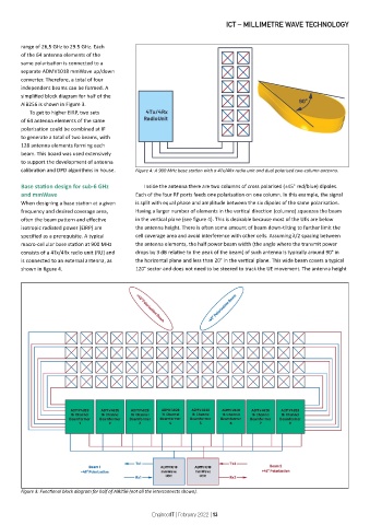
calibration and DPD algorithms in house. Figure 4: A 900 MHz base station with a 4Tx/4Rx radio unit and dual polarised two-column antenna.
Base station design for sub-6 GHz Inside the antenna there are two columns of cross polarised (±45° red/blue) dipoles.
and mmWave Each of the four RF ports feeds one polarisation on one column. In this example, the signal
When designing a base station at a given is split with equal phase and amplitude between the six dipoles of the same polarisation.
frequency and desired coverage area, Having a larger number of elements in the vertical direction (columns) squeezes the beam
often the beam pattern and effective in the vertical plane (see figure 4). This is desirable because most of the UEs are below
isotropic radiated power (EIRP) are the antenna height. There is often some amount of beam down-tilting to further limit the
specified as a prerequisite. A typical cell coverage area and avoid interference with other cells. Assuming λ/2 spacing between
macro-cellular base station at 900 MHz the antenna elements, the half power beam width (the angle where the transmit power
consists of a 4Tx/4Rx radio unit (RU) and drops by 3 dB relative to the peak of the beam) of such antenna is typically around 90° in
is connected to an external antenna, as the horizontal plane and less than 20° in the vertical plane. This wide beam covers a typical
shown in figure 4. 120° sector and does not need to be steered to track the UE movement. The antenna height
Figure 3: Functional block diagram for half of AiB256 (not all the interconnects shown).
EngineerIT | February 2022 | 13