
Page 56 - Energize July 2021
P. 56
TECHNICAL
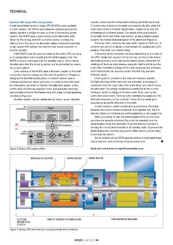
Dynamic MV rotary UPS configuration coupler, which consists of two parts rotating about the same axis.
A well-established dynamic rotary UPS (RUPS) is also available The inner rotor is fixed to the shaft connected to the MA, while the
in a MV version. The RUPS uses rotational inertia to provide the outer rotor, which is of much higher mass, rotates on its own set
energy needed to bridge the start-up time of the backup power of bearings at a different speed. The speed of the outer section
system. The RUPS uses a synchronous motor/alternator (MA) is normally twice that of the inner section, giving a relative speed
driven by the energy stored in an inertial device to bridge the equal to the normal rotational speed of the alternator (Figure 3).
start-up time. The use of an alternator makes it possible to provide The inner rotor, driven by the main shaft, rotates at 1500 rpm. It
a high-power UPS without the need for high-power converter or contains two sets of windings: a three-phase AC winding and a DC
inverter circuitry. winding. The outer rotor rotates freely.
A MV RUPS uses the same principle as the static UPS, by using The inertial device switches functions depending on the state of
a LV configuration and converting to MV at the supply level. The the UPS. Under start-up and normal running conditions the motor/
RUPS is usually collocated with the standby engine, which drives alternator acts as a motor driving the inertial device, where the AC
the alternator after the bridging period, and is connected by means windings of the inner rotor create a magnetic field which drives the
of a clutch system. outer rotor. The field windings of the outer device are not activated,
Early versions of the RUPS used a flywheel coupled to the shaft and it behaves like an induction motor. The MA only provides
to provide rotational energy, but this had the problem of frequency frictional losses.
droop as the flywheel slowed down. A modern version uses a Under grid-fail conditions, the roles are reversed, and the
freestanding flywheel-driven generator, or a battery bank followed DC field windings of the inner rotor are activated, and energy is
by a frequency converter to maintain the alternator speed. In this transferred from the outer rotor, driving the inner rotor which drives
combination the MA has separate motor and generator windings the alternator. The energy transferred is controlled by the current
and provides power to the freestanding unit under normal operating flowing in the DC windings of the inner rotor. Thus, even as the
conditions (Figure 2). outer rotor slows down, the inner rotor maintains its speed and the
Another version uses an inertial device, known as an induction alternator frequency will be constant. Power for the windings is
supplied by an exciter attached to the shaft.
In both versions, under normal running conditions, the motor
behaves like a synchronous condenser, and together with the line
inductor, filters out disturbances and irregularities on the supply line.
When grid power is lost, the diesel engine starts up and once
synchronous speed is achieved, the clutch is operated, and the
diesel engine drives the alternator. Once the standby machine is
running the inertial device reverts to its standby state. To prevent the
diesel engine from starting during short interruptions, a short delay
is built into the system.
Some versions of the RUPS operate without a collocated diesel
engine and are used to provide bridging power only. n
Figure 2: Rotary UPS system (Piller) Send your comments to rogerl@nowmedia.co.za
Figure 3: Rotary UPS with induction coupling inertial device (Hitachi)
energize | July 2021 | 54