
Page 55 - Energize July 2021
P. 55
TECHNICAL
Medium voltage UPS systems
for large IT and industrial power
system protection
by Mike Rycroft, Now Media
ninterruptible power supplies, (UPSs) used in IT servers In the LI configuration, the inverter is only used to carry the
and power-sensitive industrial processes must bridge the load for a short period and is not subjected to the continuous
Uchangeover from grid power to standby power, and protect variations that the mains disconnect switch experiences. In a
against poor power quality, such as voltage sags and surges. The double conversion UPS, the inverter is subject to load variations
bridging time required ranges from seconds to minutes. Most continuously, requiring a much higher rating.
centralised 3-phase UPS systems in use today operate in the low Storage may take the form of a battery, ultracapacitor or
voltage range. The increasing size of server and industrial power-critical mechanical flywheel. The modular design of a LI UPS allows
installations and the increasing requirement for uninterrupted power, replacement of the LV grid-to-load interface with MV components,
has resulted in larger UPS systems with associated challenges. keeping the basic parts of the UPS and the storage element the same
The typical constraining factor of large low voltage (LV) facilities as for LV applications. In this way the good and familiar experience with
is the current limit of LV switchgear and busbars. Low voltage power the functionality and maintainability of a reliable LV UPS is maintained.
distribution at high power levels carries with it the penalty of higher During normal operation, the load is fed directly from the incoming
losses and higher distribution cable and switchgear costs. In addition, supply. The inverter’s DC output maintains the storage device in
the need to place LV UPS systems near the equipment being served a state of full charge. When the supply fails, the UPS provides
creates space problems. a seamless transfer to standby power. In addition to providing
Distributing uninterrupted power at a higher voltage solves most bridging power, the MV UPS acts as a power conditioner, correcting
of these problems. Medium voltage (MV) UPS systems carry lower any power quality problems on the incoming supply. Correction is
currents and thus use smaller sized cables and lighter switchgear. In achieved by the interaction of the line reactor and the inverter.
many cases, MV UPSs can be installed close to the standby plant in a In addition to supplying power to the load under grid-fail
location outside the facility. It is easier for data centres to use MV UPS conditions, some UPS systems can provide grid support by
systems to provide backup power to an entire facility, including chillers lowering the load on the grid, even when the grid is available. This
and other mechanical infrastructure as well as the IT equipment. Using is accomplished by supplying part or all of the load requirement and
medium voltage power protection simplifies the design of power supplying excess power to the grid.
distribution, requiring fewer transformers, less cable and switchgear.
This makes the system easier to maintain, manage and supervise.
These factors are driving a move to MV UPS systems. Available MV
UPS systems usually operate between 6,6 kV and 24 kV and are available
in both static and dynamic configurations from several suppliers.
Static MV UPS
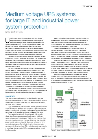
The most common configuration is the line interactive or single
conversion mode as shown in Figure 1. Lineinteractive (LI) is preferred
to the double conversion mode used in LV applications because of
the power levels involved.
Large industrial and IT electrical loads present several challenges.
One of the common problems is inrush current which occurs when a
motor or transformer is switched on. In the case of a motor this inrush
current can be six times the nominal current draw of the motor.
Power protection devices find handling such high currents
challenging. These high currents are largely reactive which can
cause voltage drops if not mitigated. This is an area where the single
conversion topology is strong. For most of the time, when the utility
power is within tolerance, the utility disconnect switch of the UPS
carries the load current. The SCRs in the utility disconnect switch
can carry a significant overload. This overload capacity, together with
a low voltage drop across the SCR, makes powering these current
inrushes possible. Figure 1: Typical static MV UPS configuration (ABB)
energize | July 2021 | 53