
Page 39 - Energize August 2021
P. 39
TECHNICAL
by restricting the core flux density to the lower values by using a Eddy current loss
relatively larger x-section. Thus, the ratio of iron loss to copper loss Eddy current is a current circulating in the magnetic core of the
is reduced. transformer due to an electromotive force (EMF) induced in the
core by stray magnetic fields. The value of the eddy current and
Efficiency improvement the resulting losses are dependent on the resistivity of the core
Transformer losses consist of resistive or load losses, and core material and are also proportional to the square of the thickness of
losses. Efficiency can be improved by reducing these losses. Well the laminations. Eddy current losses can be reduced by reducing the
known and well proven methods for reducing transformer losses thickness of the core material layers or laminations.
include using more material in the core and windings and using
material with better properties. The most significant improvement in transformer core losses has
been in the reduction of hysteresis losses by the use of higher-grade
Resistive losses core materials. Two approaches exist:
2
Heat losses, or I R losses, occur in the winding materials and • The use of amorphous metal material for the whole core material
contribute the largest part of the load losses at full load. The • The use of composite cores consisting of different materials
transformer load current cannot be changed, and resistive losses
can only be reduced by reducing the resistance of the winding Amorphous metal cores
conductors, by increasing the cross section. This will result in larger Amorphous core material (AM) offers both reduced hysteresis loss
coils and possibly a larger core size to accommodate the coils, and eddy current loss because this material has a random grain and
leading to an overall larger transformer and higher material costs. magnetic domain structure which results in high permeability, which
The savings in energy need to be balanced with the higher cost of ensures a narrow hysteresis curve compared to conventional cold-
the coils and the core. Material with a lower resistivity will generally rolled grain-oriented (CRGO) steel.
incur higher costs and this needs to be balanced with savings. Amorphous metal is an alloy with a non-crystalline structure
produced by ultra-rapid quenching (about 1 x 10 ℃ per second)
6
Core losses or no-load losses of molten alloy. Because amorphous metal has no anisotropic
No-load losses are caused by the magnetising current needed to properties, which originate from a crystalline structure, and there
energise the core of the transformer, and do not vary according are no crystalline grain boundaries to prevent motion of magnetic
to the loading on the transformer. They are constant and occur domain walls, it shows excellent magnetic properties such as high
24 hours a day, 365 days a year, regardless of the load, hence the permeability and low loss.
term no-load losses. Hysteresis losses and eddy current losses Amorphous metal material used in distribution transformers
contribute over 99% of the no-load losses, while stray eddy current, consists of an alloy of ferrous (Fe, cobalt) and nonferrous materials
2
dielectric losses and I R losses due to no-load current are small and (aluminium, copper, nickel, tin, or zinc) formed in a manner that
consequently often neglected. Thinner lamination of the core steel prevents the development of a grain structure. AM core material
reduces eddy current losses. has a much lower hysteresis coefficient than CRGO as shown in
The biggest contributor to no-load losses is hysteresis losses. Figure 4. Furthermore, losses due to harmonics are lower with
The Greek word, hysteresis, means “to lag” and refers to the fact AM-cored transformers than with CRGO types.
that the magnetic flux lags behind the magnetic force. Hysteresis is Amorphous material is manufactured and supplied in thin
the retention of magnetic domain orientation after the magnetisation continuous strips and the transformer windings are made up of
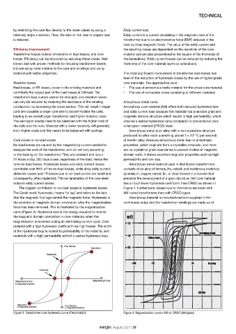
force has been removed. This is illustrated by the magnetisation
curve (Figure 3). Hysteresis loss is the energy required to reverse
the magnetic domain orientation in core materials when the
magnetisation is reversed during an alternating current cycle. Core
material with a high hysteresis coefficient has high losses. The width
of the hysteresis loop is related to permeability of the material, and
materials with a high permeability exhibit a narrow hysteresis loop.
Figure 3: Transformer core hysteresis curve (Electrical4U) Figure 4: Magnetisation curves AM vs CRGO (Metglass)
energize | August 2021 | 37