
Page 41 - Energize August 2021
P. 41
TECHNICAL
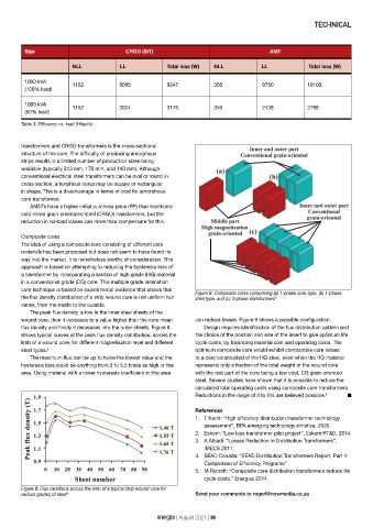
Size CRGO (SIT) AMT
NLL LL Total loss (W) NLL LL Total loss (W)
1000 kVA
1152 8095 9247 350 9750 10100
(100% load)
1000 kVA
1152 2024 3176 350 2438 2788
(50% load)
Table 3: Efficiency vs. load (Hitachi)
transformers and CRGO transformers is the cross-sectional
structure of the core. The difficulty of producing amorphous
strips results in a limited number of production sizes being
available (typically 213 mm, 170 mm, and 140 mm). Although
conventional electrical steel transformers can be oval or round in
cross-section, amorphous cores may be square or rectangular
in shape. This is a disadvantage in terms of cost for amorphous
core transformer.
AMDTs have a higher initial purchase price (PP) than traditional
cold-rolled grain-orientated steel (CRGO) transformers, but the
reduction in no-load losses can more than compensate for this.
Composite cores
The idea of using a composite core consisting of different core
materials has been proposed but does not seem to have found its
way into the market. It is nonetheless worthy of consideration. This
approach is based on attempting to reducing the hysteresis loss of
a transformer by incorporating a section of high grade (HG) material
in a conventional grade (CG) core. This multiple grade lamination
core technique is based on experimental evidence that shows that
Figure 9: Composite cores comprising (a) 1-phase core type, (b) 1-phase
the flux density distribution of a strip wound core is not uniform but shell type, and (c) 3-phase transformers 4
varies, from the inside to the outside.
The peak flux density is low in the inner steel sheets of the
wound core, then it increases to a value higher than the core mean can reduce losses. Figure 9 shows a possible configuration.
flux density and finally it decreases into the outer sheets. Figure 8 Design requires identification of the flux distribution pattern and
shows typical curves of the peak flux density distribution, across the the choice of the position and size of the insert to give optimum life
limb of a wound core, for different magnetisation level and different cycle costs, by balancing material cost and operating costs. The
steel types. 4 optimum composite core would exhibit comparable core losses
The maximum flux can be up to twice the lowest value and the to a core constructed of the HG steel, even when the HG material
hysteresis loss could be anything from 3 to 5,5 times as high in this represents only a fraction of the total weight of the wound core
area. Using material with a lower hysteresis coefficient in this area with the rest part of the core being a low cost, CG grain-oriented
steel. Several studies have shown that it is possible to reduce the
calculated total operating costs using composite core transformers.
Reductions in the range of 3 to 5% are believed possible. 4 n
References
1. T Koch: “High efficiency distribution transformer technology
assessment”, BPA emerging technology initiative, 2020.
2. Eskom: “Low loss transformer pilot project”, Eskom RT&D, 2014.
3. A Albadi: “Losses Reduction In Distribution Transformers”,
IMECS 2011.
4. SEAD Canada: “SEAD Distribution Transformers Report, Part 1:
Comparison of Efficiency Programs”
5. M Rycroft: “Composite core distribution transformers reduce life
cycle costs.” Energize 2014.
Figure 8: Flux variations across the limb of a typical strip wound core for
various grades of steel 4 Send your comments to rogerl@nowmedia.co.za
energize | August 2021 | 39