
Page 20 - EngineerIt April 2021
P. 20
ELECTRONICS
TVS—Transient voltage suppressor been correctly sized, the downstream circuitry must be capable
This is a relatively simple device that helps to protect of handling the clamped voltage, resulting in increased voltage
downstream circuitry from high voltage spikes on the power rating requirements downstream.
supply. It can be broken into several different types, which have
a wide range of characteristics (Table 1 is in order of response In-line fuse
time, smallest to largest). Overcurrent protection can be implemented using the ubiquitous
in-line fuse with a fuse blow rating at some margin above nominal
— for example, 20% higher than the maximum rated current (the
Table 1. Response time for different transient voltage
suppressor devices percentage will depend on the type of circuit as well as the typical
operational loads expected). The biggest problem with fuses,
Transient Voltage Suppressor Device Response Time of course, is that they must be replaced once blown. Time and
cost savings resulting from fuses’ simple design can be incurred
TVS Diodes ~1 ps later because of relatively complex maintenance, especially if the
application is physically hard to reach. Maintenance requirements
Metal-Oxide Varistor (MOV) ~1 ns can be reduced with alternate fuses, such as resettable fuses,
which utilise a positive temperature coefficient to open the circuit
Avalanche Diode/Zener Diode <1 µs
when a larger than normal current passes through the device (the
increased current level increases the temperature, resulting in a
Gas Discharge Tube (GDT) <5 µs
sharp increase in resistance).
Maintenance issues aside, one of the biggest problems with
Although these feature a range of constructions and fuses is their reaction time, which can vary widely depending
characteristics, they all operate in a similar manner: shunting the on the type of fuse selected. Fast blow fuses are available
excess current when the voltage exceeds the device threshold. A but clearing time (time to open the circuit) can still range from
TVS clamps the voltage at the output to the rated level within a hundreds of microseconds to milliseconds, so the circuit designer
very short period of time. A TVS diode, for example, can respond must consider the energy released over these extended times to
in as low as picoseconds’ time, while a GDT can take a few micro- ensure that downstream electronics can survive.
seconds to respond but can handle much larger surges.
Figure 3 shows the simple implementation of a TVS diode to Series diode
protect a downstream circuit. Under normal operating conditions, the In some environments, circuits are exposed to supply
TVS is high impedance and the input voltage simply passes to the disconnection and reconnection — for example, in a battery-
output. When an overvoltage condition occurs at the input, the TVS operated environment. In such instances, correct polarity is not
becomes conductive and responds by shunting the excess energy guaranteed in reconnection of the supply. Polarity protection can
to ground (GND), clamping the voltage seen by the downstream be achieved by adding a series diode on the positive supply line
load. The rail voltage rises above the typical operation value but is of the circuit. While this simple addition is effective in protecting
clamped to a value at a safe level for any downstream circuitry. against reverse polarity, the voltage drop of the series diode
Although TVS devices are effective in suppressing very high results in commensurate power dissipation. In relatively low
voltage excursions, they are not immune to damage when faced current circuits, the trade-off is minimal, but for many modern high
with sustained overvoltage events, resulting in a requirement for current rails, an alternative solution is required. Figure 4 shows an
regular device monitoring or replacement. Another concern is that update to Figure 3, showing both the TVS and the added series
a TVS can fail and thus crowbar the input supply. Also, depending diode to protect against the reverse polarity connection.
on the energy involved, they can be physically large to match
with margin, increasing the solution size. Even when a TVS has
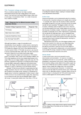
Figure 4: Adding a series diode protects against reverse polarity,
Figure 3: Protecting against voltage surges with a traditional TVS but the voltage drop of the diode can be a problem in high
solution. current systems.
EngineerIT | April 2021 | 18