
Page 22 - EngineerIt April 2021
P. 22
ELECTRONICS
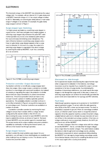
The threshold voltage of the MOSFET then determines the output
voltage limit. For example, with an internal 31.5 V gate clamp and
a MOSFET threshold voltage of 5 V, the output voltage is limited
to 26.5 V. Alternately, an external gate clamp allows a much wider
range of voltages to be selected. An example of a gate clamp
surge stopper is shown in Figure 7.
Surge stopper type: Switching
For higher power applications, a switching surge stopper is
a good choice. Like linear and gate clamp surge stoppers, a
switching surge stopper fully enhances the pass FET under
normal operation to provide a low resistance path between
the input and output (minimising power dissipation). The
main difference between a switching surge stopper and a
linear or gate clamp surge stopper appears when a surge
event is detected. In the event of a surge, the output of a
switching surge stopper is regulated to the clamp voltage
by switching the external MOSFET, much like a switching
dc-to-dc converter.
Figure 9: The LTC4368, a protection controller.
Figure 8: The LTC7860, a switching surge stopper. Disconnect vs. ride-through
Some applications require disconnecting the output from the input
Protection controller: Output disconnect when a surge event is detected. In this instance, overvoltage
A protection controller is not officially a surge stopper, but it disconnect would be required. If you needed the output to remain
does stop surges. Like a surge stopper, a protection controller operational in the face of surge events, thus minimising the
monitors for overvoltage and overcurrent conditions, but instead downtime of downstream electronics, you would require the surge
of clamping or regulating the output, the protection controller stopper to ride through the surge event. In this case, a linear or a
disconnects the output immediately to protect downstream switching surge stopper can achieve this functionality (provided the
electronics. This simple protection circuit can have a very power levels were reasonable for the topology and FET selected).
compact footprint, suitable for battery-operated, portable
applications. The LTC4368 protection controller is shown in Fault timer
a simplified schematic in Figure 9, along with its response to Ride-through operation requires some protection for the MOSFET
an overvoltage event. Protection controllers are available in a against persistent surges. To remain within the safe operating
number of variants. area (SOA) of the FET, a timer can be implemented. The timer is
A protection controller operates by monitoring the input essentially a capacitor to ground. When an overvoltage condition
voltage to ensure that it remains within a voltage window occurs, an internal current source starts to charge this external
configured by the resistor divider on the OV/UV pins, capacitor. Once the capacitor reaches a certain threshold voltage,
disconnecting the output via back-to-back MOSFETs when the a digital fault pin pulls low to indicate the pass transistor will soon
input is outside this window, as shown in Figure 9. The back- turn off due to the extended overvoltage condition. If the timer pin
to-back MOSFETs can also protect against a reversed input. voltage continues to rise to a secondary threshold, the GATE pin
The sense resistor at the output enables overcurrent protection pulls low to turn off the MOSFET.
capability by continually monitoring the forward current, but The rate of change of the timer voltage varies with the voltage
without a timer-based ride-through operation. across the MOSFET — that is, a shorter timer for larger voltages
and a longer timer for smaller voltages. This useful feature enables
Surge stopper features the device to ride through short overvoltage events, allowing
In order to select the most suitable surge stopper for your downstream components to remain operational while protecting
application, you will need to know what features are available and the MOSFET from damage by longer-lasting overvoltage events.
what challenge they are helping to solve. The devices can be Some devices feature a retry function, enabling the device to turn
found at the parametric table. on the output again after a cooling down period.
EngineerIT | April 2021 | 20