
Page 21 - EngineerIt April 2021
P. 21
ELECTRONICS
Filters using inductors and capacitors of the N-channel MOSFET to clamp the output voltage of the
The passive solutions discussed so far all limit the amplitude of MOSFET at the level set by the resistor divider.
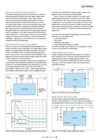
the events passed through but generally capture larger events Figure 5 shows a simplified schematic of a surge stopper
while leaving some smaller spikes to pass. These smaller implementation, along with the results of a 100 V input surge
transients can still cause damage to downstream circuitry, so on a nominal 12 V rail. The output of the surge stopper circuit is
additional passive filters are required to clean the line. This is clamped to 27 V for the duration of the surge event. Some surge
achievable using discrete inductors and capacitors, which must stoppers also monitor for overcurrent conditions using a series
be sized to attenuate the voltage at the unwanted frequencies. sense resistor (the circuit breaker in Figure 5), and adjust the gate
Filter design requires test and measurement before design to of the N-channel MOSFET to limit the current presented to the
ascertain the size and frequency before the filter can be correctly output load.
sized. The drawbacks of this path are the cost of BOM and real
estate requirements — the board area and cost of the components There are four broad types of surge stopper, classified by their
required to achieve the level of filtering — as well as the need for response to an overvoltage event:
overdesign — rating the component tolerances to compensate for • Linear surge stopper
changes over time and temperature. • Gate clamp
• Switching surge stopper
Active protection using a surge stopper • Output disconnect protection controller.
One way to overcome the challenges and disadvantages of the The choice of surge stopper depends on the application, so let’s
passive protection solutions described is to instead utilise a surge compare their operation and advantages.
stopper IC. A surge stopper eliminates the need for bulky shunt
circuitry (TVS devices, fuses, inductors and capacitors) with an Surge stopper type: Linear
easy-to-use controller IC and a series N-channel MOSFET. Surge A linear surge stopper drives the series MOSFET much like a
stopper controllers can greatly simplify system design since there linear regulator would, limiting the output voltage to the pre-
are few components to size and qualify. programmed safe value, dissipating excess energy in the
A surge stopper continuously monitors the input voltage and MOSFET. To help protect the MOSFET, the device limits the
current. Under nominal operating conditions, the controller drives time spent in the high dissipation region by implementing a
the gate of an N-channel MOSFET pass device fully on, providing capacitive fault timer.
a low resistance path from the input to the output. When an
overvoltage or surge condition occurs — with a threshold dictated
by a feedback network at the output — the IC regulates the gate
Figure 6: The LT4363, a linear surge stopper.
Surge stopper type: Gate clamp
The gate clamp surge stopper operates by utilising either an
internal or external clamp (31.5 V or 50 V internal, for example, or
an adjustable external clamp) to limit the gate pin to this voltage.
Figure 5: A high level diagram of a surge stopper implementation. Figure 7: The LTC4380, a gate clamp surge stopper.
EngineerIT | April 2021 | 19