
Page 61 - Energize September 2021 HR
P. 61
TECHNICAL
Active PF correction devices
The most common device is the static compensator, or STATCOM,
also known as the static VAR generator (SVG). Primarily used in
high power MV and HV applications, the device is now finding
application in medium power MV and LV distribution networks,
as well as industrial and commercial site applications, in the form
of the distribution STATCOM or D-STATCOM (DS). Devices from
as low as 10 kVAr are available. The DS has the additional benefit
that it can compensate for harmonics in the load current as well as
reactive current.
Figure 9: Single phase DS 4
The distribution STATCOM
The distribution STATCOM (DS) is a device for reactive power
compensation in electric distribution networks. It presents
advantages over conventional methods, since it avoids power
resonances and can provide a continuous range of compensation,
reaching a power factor near to unity.
These devices are finding increasing application in distribution
networks, especially where embedded generation is involved. Figure 10: Reactive power generation 4
Similar to the HV STATCOM in operation, the DS incorporates a
number of additional features which are specifically required to
address distribution network problems, such as harmonic reduction,
voltage regulation, etc.
The DS is a parallel connected device which synthesises the
required reactive current using electronic devices such as multilevel
converters. A typical layout of a DS is shown in Figure 8.
The DS consists of an inverter, DC link capacitance C which
provides the DC voltage for the inverter, coupling inductance
L used for reactive power exchange between the DS and the
power system and a control unit to generate PWM signals for the
switches of the inverter.
Figure 11: V-I Characteristic of a distribution STATCOM 4
D-STATCOM operation
The active and reactive power transfer between the power system
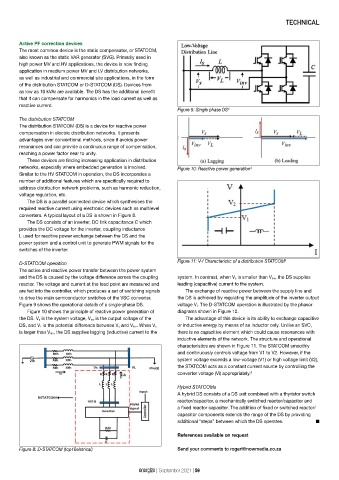
and the DS is caused by the voltage difference across the coupling system. In contrast, when V s is smaller than V inv, the DS supplies
reactor. The voltage and current at the load point are measured and leading (capacitive) current to the system.
are fed into the controller, which produces a set of switching signals The exchange of reactive power between the supply line and
to drive the main semiconductor switches of the VSC converter. the DS is achieved by regulating the amplitude of the inverter output
Figure 9 shows the operational details of a single-phase DS. voltage V i. The D-STATCOM operation is illustrated by the phasor
Figure 10 shows the principle of reactive power generation of diagrams shown in Figure 10.
the DS. V s is the system voltage, V inv is the output voltage of the The advantage of this device is its ability to exchange capacitive
DS, and V L is the potential difference between V s and V inv. When V s or inductive energy by means of an inductor only. Unlike an SVC,
is larger than V inv, the DS supplies lagging (inductive) current to the there is no capacitive element which could cause resonances with
inductive elements of the network. The structure and operational
characteristics are shown in Figure 11. The STATCOM smoothly
and continuously controls voltage from V1 to V2. However, if the
system voltage exceeds a low-voltage (V1) or high voltage limit (V2),
the STATCOM acts as a constant current source by controlling the
converter voltage (Vi) appropriately. 5
Hybrid STATCOMs
A hybrid DS consists of a DS unit combined with a thyristor switch
reactor/capacitor, a mechanically switched reactor/capacitor and
a fixed reactor capacitor. The addition of fixed or switched reactor/
capacitor components extends the range of the DS by providing
additional “steps” between which the DS operates. n
References available on request
Figure 8: D-STATCOM (top10eletrical) Send your comments to rogerl@nowmedia.co.za
energize | September 2021 | 59