
Page 58 - Energize September 2021 HR
P. 58
TECHNICAL
Power factor correction systems for
low and medium voltage networks
by Mike Rycroft, Now Media
Power factor (PF) is often overlooked in power quality standards but is still of great significance and can
affect both the supply and the consumer network. With the development of flexible AC transmission
systems (FACTS) devices for LV and MV sectors, there is now a wide range of capable PF correction or
compensation equipment for the low and medium voltage sector.
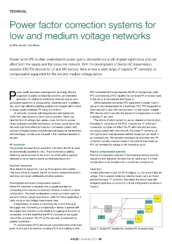
ower quality becomes more important as energy efficient PFC connected at the load handles the PF of the load only, while
equipment is added to industrial networks, as embedded PFC connected at a PCC handles the combined PF of several loads
Pgeneration is installed in distribution networks and as own- at the site or in the network (see Figure 1).
generation equipment is introduced by industrial users. In addition, While load point connected PFC equipment is usually fixed in
the use of high efficiency lighting systems has brought with it a host size and only compensates for a fixed load, PCC PFC equipment is
of power quality problems, PF being one of them. often required to deal with varying loads. For this reason, variable
All networks, however well designed and well maintained, PFC devices which can alter the amount of compensation to match
suffer from disturbances of some form or another. These may a varying PF are used.
take the form of voltage dips, spikes, noise, harmonics, power The choice of which system to use will depend on the situation.
factor variations and EMC interference. Of these, power factor has Providing PF correction at the PCC improves the PF of the grid
the most significant effect as it results in increased current, with connection, but does not affect the PF within the site and does
resultant increased losses and potential overloading of transformers not reduce losses within the network. Providing PF correction at
and switchgear, as well as an increase in the maximum demand on the input to each load decreases network losses but can result in
the grid. an increased cost. The decision is primarily an economic one. PF
correction can also increase losses in the case of linear loads as
PF correction PFC will increase the voltage at the connection point.
The purpose of power factor correction is to return the PF as close
as economically possible to unity. This is achieved by adding Passive compensation systems
balancing reactive power to the circuit, by either adding reactive Passive compensation consists of fixed reactive devices such as
elements or using reactive power synthesising equipment. capacitors and inductors. Devices may be used singly in a fixed
configuration or as multiple units in a switched configuration.
Electronic equipment
Most electronic equipment, such as IT equipment and variable Capacitors
frequency drives for motors, has PF correction components built-in In many industrial circuits, the PF is lagging, i.e., the current lags the
and does not require additional correction systems. voltage. This is caused mainly by inductive loads, such as motors
and transformers. PF correction here takes the form of specially
Shunt/parallel and series compensation systems designed capacitors connected in a shunt configuration as shown in
Where PF correction is required, this is usually provided by Figure 2.
connecting either reactive or electronic devices in a shunt or series
configuration. The shunt configuration is most commonly used for
low and medium voltage applications, while the series application is
used mainly in high voltage transmission lines.
Compensation is based on modifying the current flowing in
the supply line. Connecting a compensation device in parallel with
the supply adds reactive current (leading or lagging) at the point of
connection, with the result that the PF is improved on the supply
side of the connection. The PF on the load side is unaffected by
parallel connection.
PF compensation (PFC) devices are connected either at the load
point, or at a point of common coupling (PCC) of a building or site. Figure 1: Central PFC handles the combined PF of several loads
energize | September 2021 | 56