
Page 60 - Energize September 2021 HR
P. 60
TECHNICAL
When capacitors are switched in or out of a circuit, the power Static VAR compensators
system faces transient over-voltages, which theoretically could Static VAR compensators (SVC) were previously used in HV
reach phase-to-ground peak values of approximately 2 p.u. (refer to networks mainly but are now finding application in LV distribution,
Figure 4). This situation could be aggravated when other capacitor industrial and commercial networks. The SVC consists of a
banks are located in the same power system and could result in combination of TCR and TSC devices, operating under control
transient over-currents of great magnitude and high frequencies, of a switching device as shown in Figure 7. The unit may consist
which are able to considerably exceed the nominal current of the of a single reactive device or switched banks of capacitors and
capacitor bank for some milliseconds. inductors. Although they use thyristor switching, they are still
The solution is to control switching so that connection occurs at basically passive devices. Mechanically switched banks can be
the point where the supply voltage matches the capacitor voltage, included to increase the total reactive power support outside the
and disconnection occurs at the point where the capacitor voltage dynamic range of the TSC or TRC.
is zero. This method requires monitoring and control circuitry and Most common topologies for SVCs are: TCR/FC or TCR/TSC/
the use of thyristors. FC. The main advantage for using a topology with TSC branch(es) is
Inductive reactors do not experience high transients when to reduce the losses by reducing the filter size.
switched in and out and switching can occur at any point of the
cycle. This allows the inductance to be switched on for part of the
cycle (varying the firing angle) relying on the thyristors to switch off
at the zero-voltage crossover. By controlling the firing angle of the
thyristor as shown in Figure 5, it is possible to vary the effective
inductance of the reactor. Thyristor-controlled reactors do not
generate transients, but they do generate harmonic currents at
firing angles above 90°. These harmonics need to be dampened by
individually tuned filter circuits.
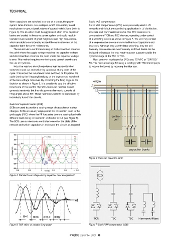
Switched capacitor banks (SCB)
SCBs are used to provide a varying range of capacitance in step
changes. SCBs are usually employed at the connection point to the
grid supply (PCC) where the PF fluctuates due to a varying load with
different loads being connected in and out of circuit (see Figure 6).
The SCB uses an electronic controller to monitor the state of the
network and switch capacitors in and out of the circuits as required.
Figure 6: Switched capacitor bank 2
Figure 4: Transient overvoltage during capacitor bank energisation 3
Figure 5: TCR effect of variable firing angle 6 Figure 7: Static VAR compensator (ABB)
energize | September 2021 | 58