
Page 45 - Energize September 2021 HR
P. 45
TECHNICAL
These findings were verified by the national energy regulator which
oversees the compliance of all the RPPs. Therefore, the RPP was
liable to reduce these harmonic levels to within acceptable limits,
within a certain time frame.
Mitigation solution alternatives
Mitigating harmonic content on a supply line can be achieved
via various methods. For example, a passive harmonic filter
can be designed which involves capacitance and inductance
elements, tuned towards the harmonic current frequency to be
trapped and dissipated, rather than to be let through to the grid.
Consideration should be given to unwanted resonance conditions
at nearby harmonic orders. Passive harmonic filtration is the
industry standard throughout the world for harmonic generators,
such as mining and commercial operations, which have very well
documented and steady state harmonic emissions. It is generally
easy and relatively cheap to implement passive harmonic filters, as
these filters are made from discrete components (capacitors and
inductors). These filters also have some fundamental frequency
losses. These operating losses reduce the kWh output of the wind
farm accordingly.
Over the lifetime of the wind farm, these losses would
accumulate into a large monetary value, which would be
much greater than the initial cost and operating losses of
an active type filtering system. In this case, these passive
filters were not an option, as the harmonics in question were
too close to the fundamental frequency (second) and were
constantly changing based on the output of the RPP (based
on wind speed).
The operating losses calculated were high and the RPP also
has very strict resonance compliance conditions which limited the
implementation of passive harmonic filtration equipment. Passive
harmonic filters also take up a significant amount of space due to
their required safety clearances. Many RPP’s do not have the real
estate available for a passive filtering solution with multiple steps
catering for each harmonic order.
The second option for harmonic mitigation would be via
active harmonic filters, whereby offending harmonic currents
are cancelled or reduced via injection of inverse harmonic
currents in real time. This is an attractive solution if the offending
harmonic currents are at multiple harmonic orders, if the
orders may vary over time, or include very low harmonic orders
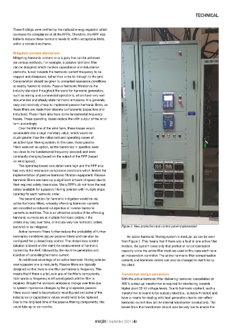
(second) to be mitigated. Figure 2: New protection and control panel implemented
Active harmonic filters further reduce the probability of further
resonance conditions (as per passive filters) and can also be An active harmonic filtering system is modular, as can be seen
configured for a closed loop control. The closed loop control from Figure 1. This means that if there was a fault in one active filter
solution is based on the real-time measurement of harmonic module, the system loses only that portion of its compensation
content by the AHF, followed by the real time generation and capacity since the active filter modules used in this case each have
injection of cancelling harmonic current. an independent controller. The active harmonic filter compensation
An additional advantage of an active harmonic filtering solution currents and harmonic orders can also be changed in real time by
over a passive one is modularity. Passive filters are typically the client.
designed so that there is one filter per harmonic frequency. This
means that if there is a failure in any of the filter’s components, Transformer design parameters
that harmonic frequency is left unmitigated until the filter is With the active harmonic filter delivering harmonic cancellation at
repaired. Should the harmonic emissions change over time due 400 V, a step-up transformer is required for interfacing towards
to system impedance changes by the grid operator, passive higher plant 33 kV voltage levels. Due to harmonic content, such a
filters would need to be physically reconfigured and some of the transformer is bound to be suitably rated (i.e., suitable K-factor) and
inductance or capacitance values would need to be replaced. have a means for dealing with heat generation due to skin-effect
Due to the long lead time of the passive filtering components, this harmonic current flow (at the internal transformer conductors). The
could take up to six months. losses from this transformer should also be very low to enable the
energize | September 2021 | 43