
Page 50 - Energize September 2021 HR
P. 50
TECHNICAL
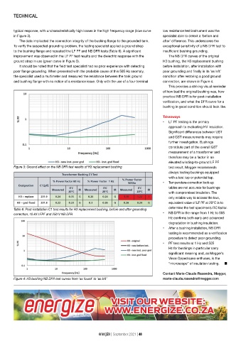
typical response, with uncharacteristically high losses in the high frequency range (blue curve low resistance test instrument was the
in Figure 3). specialist able to detect a ‘before and
The data implicated the connection integrity of the bushing flange to the grounded tank. after’ difference. This underscores the
To verify the suspected grounding problem, the testing specialist applied a ground strap exceptional sensitivity of a NB DFR test to
to the bushing flange and repeated the LF PF and NB DFR tests (Table 6). A significant insufficient bushing grounding.
improvement was observed in the LF PF test results and the dielectric response with the The NB DFR curves of the original
ground strap in use (green curve in Figure 3). H3 bushing, the H3 replacement bushing
It should be noted that the field test specialist had no prior experience with detecting before installation, after installation with
poor flange grounding. When presented with the probable cause of this 505 Hz anomaly, poor grounding and finally in its ‘as left’
the specialist used a multimeter and measured the resistance between the tank ground condition after restoring a good ground
and bushing flange with no notice of a resistance issue. Only with the use of a four-terminal connection, are shown in Figure 4.
This provides a striking visual reminder
of how bad the original bushing was, how
practical NB DFR is for post-installation
verification, and what the DFR curve for a
bushing in good condition should look like.
Takeaways
• LF PF testing is the primary
approach to evaluating HV insulation.
Significant differences between UST
and GST measurements may require
further investigation. Bushings
constitute part of the overall GST
measurement of a transformer and
therefore may be a factor in an
elevated winding-to-ground LF PF
Figure 3: Ground effect on the NB DFR test results of H3 replacement bushing test result. Megger recommends
always testing bushings equipped
with a test tap or potential tap.
• Temperature-correction look-up
tables are not accurate for bushings
with compromised insulation. The
only reliable way to access the true,
equivalent value of LF PF at 20°C is to
determine the test specimen’s ITC factor.
Table 6: Post-installation C1 test results for H3 replacement bushing, before and after grounding
• NB DFR in the range from 1 Hz to 505
correction, 10 kV LFPF and 250 V NB DFR
Hz confirms both early and advanced
degradation in bushing insulation.
• After a bushing installation, NB DFR
testing is recommended as a verification
procedure to detect poor grounding.
• PF test results at 1 Hz and 505
Hz for bushings in particular carry
significant meaning and, as Megger’s
Vince Oppedisano enthuses, is the
“microscope” of insulation testing. n
Contact Marie-Claude Rasendra, Megger,
Figure 4: H3 bushing NB DFR test curves from ‘as found’ to ‘as left’ marie-claude.rasendra@megger.com
energize | September 2021 | 48