
Page 52 - Energize September 2021 HR
P. 52
TECHNICAL
protection grading between multiple devices becomes an issue, a
downstream phase-to-phase fault in the next zone may appear as an
NPS fault in the upstream zone, leading to a race condition between
overly sensitive NPS in the upstream device and the conventional
overcurrent function in the circuit breaker closest to the fault.
When impedance information is hard to gather, we can rely on
the i 1 = i 2 relationship in a three-phase system during a broken
conductor fault. When a broken conductor occurs, in a perfect
theoretical model:
Or expressed as a percentage:
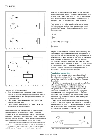
Figure 2: Simplified circuit of Figure 1
Assigned the ANSI Protection code 46BC (broken conductor), this
ratio of negative to positive sequence removes the dependency of
impedance from the calculation. This way, regardless of the load, we
have sensitivity to the broken conductor fault condition to effectively
detect the broken conductor scenario in a three-phase network.
It would be very rare for any normal network scenario on a three-
phase network to exceed 20% negative sequence current to positive
sequence. As such, it is a common starting setting for this feature
in the field, providing grading with overcurrent elements whilst
accounting for the cases of phase discontinuities.
Four-wire three-phase systems
Common in North American network topologies and the LV
distribution network in Australia, four-wire three-phase offers a
slightly different result when considering the effects of a phase
discontinuity.
By adding the neutral conductor, we introduce a complication
to the calculation because the neutral becomes a current
Figure 3: Equivalent circuit, three-wire network with a broken conductor
conductor during unbalanced conditions. Oftentimes this is
a design consideration, allowing for continuity of service to
This gives us a few key observations. two thirds of customers in the LV case, should a single phase
• Under a broken conductor scenario, the positive sequence encounter a fault, but by adding the conductor we reduce our
current is the same as the negative sequence current. When the ratio of i 2 to i 1 in the broken conductor scenario. With a neutral
conductor isn’t broken, it is 100% positive sequence and 0% conductor in play, we introduce the effect of the zero-sequence
negative sequence. impedance (see Figure 5).
• The positive and negative sequence currents are calculated Again, we are faced with an equivalent network which is very
using the same impedance. similar to the double line to ground fault, except we are considering
• The load may still be high enough that i 1 doesn’t exceed the the load impedances instead of the line impedances. If we assume
overcurrent pickup level – dangerous. that the source impedances are negligible in comparison to the load,
we could draw an equivalent circuit as in Figure 6.
Modern digital protection relays often offer both negative phase
sequence protection and overcurrent protection. For the three-
wire case, we can see that the expected negative phase sequence
component is dependent on the impedance of the load in the broken
conductor scenario. Therefore, the actual resultant negative sequence
current depends on the load topology at the time of the fault.
Pragmatically, we could consider that in theory a network should
exhibit very low negative sequence current in an un-faulted state, so
we could plausibly use this as a rationale to set the operating point
for NPS quite low. This may work in simple scenarios, but when Figure 4: A four-wire three-phase system
energize | September 2021 | 50