
Page 47 - Energize September 2021 HR
P. 47
TECHNICAL
Active harmonic filter design
The active harmonic filtering solution was constructed from modular
units. The OEM of these filtering modules is Merus Power Dynamics
OY. They are a specialist power quality and harmonic filtering
company based in Finland. RWW Engineering is the South African
partner to Merus Power Dynamics OY.
The AHF modules were installed into enclosures and fitted into
the converted container. The container was fully insulated from
external temperature variations and cooled via bulk air conditioning.
RWW Engineering completed all the required site integration
including the civil works, mechanical installation, electrical
installation, SCADA development, protection integration, switchgear
and other requirements.
The filter modules are designed using a three level IGBT
switching philosophy which increases the resolution, reduces the
losses and audible noise and has greatly improved functionality
Figure 7: Special metering CT application
compared to standard active filters on the market. Each module
has its own touch screen where the local operator can modify the
compensation requirements and parameters.
The entire system is also networked to Merus Power directly
for them to check and maintain all parameters. The end client also
has access for their own operators and maintenance personnel.
Each active harmonic filter module is individually protected via fuses
and the entire system is protected by group fuses. Each module
also has other internal protections against overcurrent, over and
undervoltage, overtemperature and so on.
Since the modules are actively controlled, they automatically
limit their output current to the maximum allowed current, unlike
passive filters which absorb harmonic currents without any control.
If due to some transient event the module current exceeds the
maximum allowed limit, the IGBTs can be shut down within a
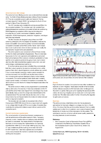
Figure 8: Second and fifth order harmonic current trend in relation to total
few microseconds to prevent damage to them or other internal
active power: pre- and post Merus A2 active harmonic filter installation
components. The overtemperature control limits each module’s
output current linearly if a threshold temperature is exceeded. The
aim is to find a current level which keeps the temperatures below the Results
allowed limit. Figure 8 shows the results of the active harmonic filter installation for
The active harmonic filters can be programmed to automatically harmonic current mitigation. Trend data to the left of the horizontal
start up after a trip. For example, if there was a transient on the HV marker indicates second and fifth harmonic order trending prior to
grid and the active filters were tripped from overvoltage, they would the switch-on period. Being set up for targeting the second and fifth
automatically start up once the voltage was restored back to the orders, the resulting mitigation can be clearly seen to the right of the
acceptable level. This automatic feature also has a limit on how marker line. The latter does conform to the limits set by the regulator
many times a trip can happen before the module is locked and user for grid-code compliance.
action is required to restart it.
The modules can also easily be repurposed into a Static Summary
Compensator (STATCOM) should this be a requirement with regards This article provides a brief introduction into the requirements
to low voltage ride-through (LVRT) on a wind plant. If needed, they and solution for harmonic mitigation at a large wind farm in South
could also be configured to balance asymmetrical currents at the Africa. It is shown that the use of an active harmonic filter is a viable
connection point. solution and is often the only solution, due to ease of scalability and
limited risk of introducing further resonance into the system. The
Current transformer requirements wind farm is now fully compliant with all power quality parameters,
The correct selection of current transformers is paramount to including harmonic current emissions. n
optimal performance of the active harmonic filters. Frequency
response, burden, transfer ratios and physical sizes should all Reference
be carefully considered. The measurement of the high order 1. Grid Connection Code for Renewable Power Plants (RPPs)
harmonic currents required the implementation of a specially connected to the Electricity Transmission System (TS) or
manufactured metering CT with a high metering accuracy. This the Distribution System (DS) in South Africa, Version 3.0,
CT was installed around the bushing of the main 132 kV/33 August 2019.
kV RPP transformer. It also has a special core construction
to accurately measure the harmonic currents that the plant is Contact Kyle Lass, RWW Engineering, Tel 011 433-8003,
emitting into the system. kjlass@rww.co.za
energize | September 2021 | 45