
Page 51 - Energize September 2021 HR
P. 51
TECHNICAL
Broken conductors and negative
sequence overcurrent protection
Information from NOJA Power
A broken conductor can be a nightmare for a power systems engineer. Most network protection
elements are designed to operate when there is too much phase current, but in the case of a broken
conductor, it’s the absence of current that is of concern. Aside from browning-out or shedding
downstream loads, broken conductors can cause fires and go undetected by conventional overcurrent
or earth fault protection relaying techniques.
ortunately, understanding the physics of the broken conductor In the AC distribution world, symmetrical components are not
network scenario is not too difficult, and while the three-wire confined to currents alone. Voltages and impedances can also be
Fand four-wire distribution network topologies yield slightly represented in sequence component format, greatly simplifying
different network responses, a sound understanding of these fault analysis. When we consider the case of broken conductors it is
concepts will help detect and protect against this fault scenario. important to acknowledge that:
• Voltage sources are confined to the positive sequence elements
Fortescue’s Symmetrical Component theory • There is equivalent positive, negative and zero sequence
Firstly, it’s worthwhile understanding Fortescue’s Symmetrical impedance for a distribution network
Component theory, which we can use to map measured
phase currents and voltages to the positive, negative and zero Three-wire three-phase systems
sequence components. This mapping process allows us to When considering the broken conductor scenario, let’s consider
ignore imbalances between phases during faults, making the fault what happens on a three-wire system first.
analysis process much easier. Fundamentally, most alternating As a first step in analysis, it’s worth understanding what the
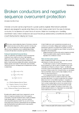
current (AC) protection techniques use this transformation process broken conductor will mean for each of the phase currents. With
to detect faults. a discontinuity in Phase A, as shown in Figure 1, we effectively
remove the current flow through that phase. Despite the three-phase
generators’ efforts to push current through the lines, we can assume
that no current flows, leaving us with a clear imbalance. We can
redraw the circuit as per Figure 2.
For the seasoned protection engineer, Figure 2 greatly
resembles the fault analysis of a phase-to-phase fault, which
generally makes sense. In a phase-to-phase fault, the un-faulted
Where: phase would seem to have infinite impedance in comparison to
a fault between the two other conductors. The only difference is
that in a phase-to-phase fault, we would only consider the line
impedance, while with a broken conductor scenario we would
consider the load impedance. For phase-to-phase faults, in the
broken conductor scenario on a three-phase line, our equivalent
circuit would become as shown in Figure 3.
By entering the values for each phasor measurement, we can
derive the magnitude and phase of each of the sequence
components. In the ideal theoretical world, a healthy distribution
feeder should exhibit no imbalance, and should therefore
only have positive sequence current. You can confirm this by
substituting a set of balanced current phasors into the equations
and checking that the result adds to zero for every equation
except the positive sequence. Figure 1: A three-wire system with a broken conductor in Phase A
energize | September 2021 | 49