
Page 46 - Energize September 2021 HR
P. 46
TECHNICAL
maximum amount of harmonic current to pass through the winding.
Therefore, the impedance should be as low as practically possible
(Z% <= 3,5%).
There should also be no phase shift over the transformer and
as such the requirement was for a star-star step up 5000 kVAR
400 V/33 kV transformer. The transformer should also be capable
of operating at high loading continuously. Another aspect in
transformer dimensioning is the harmonic voltage distortion at the
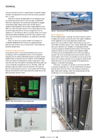
400 V bus. When the active harmonic filter modules inject harmonic
current through a transformer, there is a voltage drop over the Figure 5: Active harmonic filter and step-up transformer installation
transformer at that frequency. Hence, the proper design must ensure
that the total harmonic distortion at the 400 V bus is kept to a level Filter configuration
which does not disturb the operation of any electronics connected For this specific project, a relatively high level of harmonic current
to that bus. mitigation was required, making this one of the largest installations
Finally, the short circuit current at 400 V level needs to be for this application in the world. Sizing requirements were
considered. Splitting the 400 V side to two separate busbars determined to be at 2700 A at 400 V. This required the use of 17 x
limits the short circuit currents on those busses, which makes the 160 A Merus A2 active harmonic filter modules. All the filter modules
protection design easier. and control hardware were installed into a dedicated modified
container, properly air conditioned and located in the existing HV
Protection design parameters switchyard. Real-time communication was installed to enable
The protection system implemented should follow the client’s monitoring and remote adjustments of the control parameters as
existing bay control and protection scheme. This includes the required. The control parameters and tuning of the filter modules
integration into an existing differential protection envelope and the can be made in real time from any operator who has access to the
implementation of main and backup protection. SCADA elements secure communication network. It is not required to switch off and
should also follow the existing client system configuration. In this isolate the system for any control changes to be made and any
case, the client has a Schweitzer Engineering Laboratories (SEL) bay changes will take effect immediately.
control, differential and protection scheme. Therefore, a SEL-787 The system is scalable and can react in real time to any RPP
protection relay was used as the main protection with a second or network changes that occur. This is a great benefit over passive
SEL-751 used as backup protection. A new outdoor 40,5 kV circuit harmonic filters which are fixed in their tuning point and require
breaker was installed to switch and protect the transformer and the large infrastructure changes, which have a long lead time for any
Merus A2 active harmonic filters. modifications to the filtering parameters.
Figure 3: New client SCADA screens implemented
Figure 4: AHF SCADA screens implemented Figure 6: Merus A2 active harmonic filter modules
energize | September 2021 | 44