
Page 43 - Energize November 2022
P. 43
TECHNICAL
torque in this example depends on the current amplitude and the
number of turns on the stator windings, the strength and the size
of the permanent magnets, the air gap between the rotor and the
windings, and the length of the rotating arm.
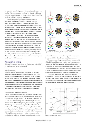
Energizing individual windings in sequence is wasteful
as only one winding out of three is energized at one time.
Better performance is obtained by energizing two windings
simultaneously so that one winding attracts and the other repels
as shown in Figure 6. At any position of the rotor, two of the three
windings are operational. This creates a complex magnetic field in
the stator, which allows smooth control of the motor. This type of
control is not possible with brushed commutator motors.
In commutation, the current in the windings is switched
from winding to adjacent winding based on the shaft position
feedback. Operation of an ECM requires knowledge of the rotor
position, and this is used to control the flow of current to the stator
windings. In a brushed motor this is provided by the mechanical
commutator fixed to the shaft. In larger motors the position of
the brushes relative to the commutator can be altered to change
the motor characteristics but this offers only limited adjustment.
An ECM motor has an internal shaft position feedback provided Figure 6: Control of rotation for a three-phase BLDC
3
by a shaft position feedback sensor of some type which feeds the
drive controller. The controller in turn switches on the appropriate that would otherwise be needed to support the sensors, and
windings at the right moment. improves reliability when dirt and humidity are present.
The sensor signal changes state at the zero-crossing point
Rotor position sensing of the BEMF, providing precise position data for commutation.
Rotor position sensing uses either Hall-effect sensors or back EMF However, as BEMF is proportional to the speed of rotation, this
sensing (known as ‘sensorless’ sensing). implies that the motor requires a minimum speed for precise
feedback. So, under very low speed conditions, such as start-up,
Hall-effect sensing different methods such as open loop are required to control the
Hall-effect sensors (HES) are devices that react to the presence motor. Figure 7 compares HES and BEMF sensing methods.
of magnetic fields and are used to detect position by sensing the A stationary motor generates no back EMF, making it
changes in the rotor magnetic field. To energize the correct stator impossible for the microcontroller to determine the position of
winding, the rotor position must be known. ECM motors typically the motor parts at start-up. The solution is to start the motor in
have three HESs mounted on the stator and use what is known as six- an open loop configuration until sufficient EMF is generated for
step commutation. When the rotor passes a sensor, it produces either the microcontroller to take over motor supervision.
a high or a low signal to indicate which rotor pole (N or S) has passed.
This switching of the three hall effect sensors (from high to low or
from low to high) provides rotor position information every 60°.
Sensorless speed and position detection
Sensors, however, cannot be used in applications where the rotor
is in a closed housing and requires minimal electrical entries, such
as a compressor or applications where the motor is immersed in
a liquid. All electric motors generate a back EMF (BEMF) due to
the movement of the windings through the associated magnetic
field. For a given motor of fixed magnetic flux and number of
windings, the BEMF is proportional to the angular velocity of the
rotor. By monitoring the BEMF, the relative positions of stator and
rotor can be determined without the need for Hall-effect sensors.
This simplifies motor construction, reducing its cost as well as
eliminating the additional wiring and connections to the motor Figure 7: HES and BEMF sensing 2
energize | November 2022 | 43