
Page 45 - Energize November 2022
P. 45
TECHNICAL
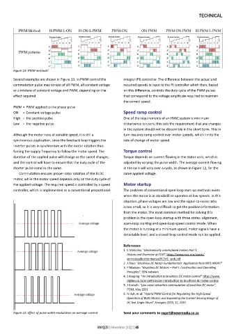
Figure 13: PWM methods 6
Several examples are shown in Figure 13. In PWM control the integral (PI) controller. The difference between the actual and
commutation pulse may consist of all PWM, all constant voltage required speeds is input to the PI controller which then, based
or a mixture of constant voltage and PWM, depending on the on this difference, controls the duty cycle of the PWM pulses
effect required. that correspond to the voltage amplitude required to maintain
the correct speed.
PWM = PWM applied to the phase pulse
ON = Constant voltage pulse Speed ramp control
High = the positive pulse One of the requirements of an HVAC system is minimum
Low = the negative pulse disturbance to users; this sets the requirement that any changes
in the system should not be discernible in the short term. This in
Although the motor runs at variable speed, it is still a turn requires ramp control over motor speeds, which limits the
synchronous application, since the feedback loop triggers the rate of change of motor speed.
inverter pulses in synchronism with the motor rotation thus
forcing the supply frequency to follow the motor speed. The Torque control
duration of the applied pulse will change as the speed changes, Torque depends on current flowing in the stator coils, which is
and the control will have to ensure that the duty cycle of the adjusted by varying the pulse width. The average current flowing
shorter pulse remains the same. in the coils will vary over a cycle, as shown in Figure 12, for the
Commutation ensures proper rotor rotation of the BLDC same applied voltage.
motor, while the motor speed depends only on the duty cycle of
the applied voltage. The required speed is controlled by a speed Motor startup
controller, which is implemented as a conventional proportional- The problem of conventional open-loop start-up methods exists
when the motor is at standstill or operates at low speeds. In this
situation, phase voltages are low and the signal-to-noise ratio
is too small, so it is very difficult to get the position information
from the motor. The most common method for solving this
problem is the open-loop startup with three states: alignment,
open-loop starting and open-loop speed control mode. When
the motor is running at a minimum speed, motor signals have a
detectable level, and a closed-loop control mode can be applied.
References
1. C Maholley: “Electronically commutated motors Part 1:
History and Overview of ECM”, https://www.rses.org/assets/
serviceapplicationmanual/ECM1_web.pdf
2. J Zhao: “Brushless DC Motor Fundamentals: Application Note MPS ANO47”
3. P Madaan: “Brushless DC Motors – Part I: Construction and Operating
Principles”, EDN network
4. S Keeping: “An introduction to brushless DC motor control” https://www.
digikey.co.za/en/articles/an-introduction-to-brushless-dc-motor-control
5. J Krotsch: “Low noise sensorless commutation of brushless DC motor”,
PCIM, May 2001
6. N Huh, et al: “Hybrid PWM Control for Regulating the High-Speed
Operation of BLDC Motors and Expanding the Current Sensing Range of
DC-link Single-Shunt”, Energies 2019, 12, 4347.
Figure 12: Effect of pulse width modulation on average current Send your comments to rogerl@nowmedia.co.za
energize | November 2022 | 45