
Page 44 - Energize November 2022
P. 44
TECHNICAL
Commutation
The drive current for a BLDC motor follows a trapezoidal
waveform, generated by on-off switching through the control
gear. For a three-phase BLDC six steps or switching phases are
used. Commutation applies current to the stator coils depending
on the position of the rotor. A typical sequence is shown in
Figure 8.
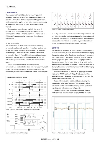
Semiconductor controllers are available from several Figure 10: 6 and 12 step commutation 5
suppliers, greatly simplifying the design of control circuitry.
Current is applied to the motor by electronic switches such as of 12-step commutation is that, despite these improvements, only
JFETs or IGBTs under control of a processor. Figure 9 shows a one of the six switches has to be modulated for the speed control
typical circuit. at any time. The PWM duty cycle can be constant throughout the
commutation step. There is no need for any sophisticated three
12 step commutation phase modulator and the switching losses remain low.
The usual method for BLDC motor commutation is six-step
commutation, where only two of the three phase windings are Controls
excited at any time. The steps change after each 60° electrical The brushless DC motor can be made to emulate the characteristics
rotation angle. A more advantageous method is the 12-step of the brushed motor, in which the speed is controlled by changing
commutation shown in Figure 10. In this case, additional states the applied voltage, rather than by changing the supply frequency.
are inserted in which all the phase windings are excited. The The supply frequency still changes but it does so as the result of
individual steps alternate after each 30° of electrical rotation the changing motor speed not the cause. Changing the voltage
angle. changes the current flowing in the stator windings which is what
Torque ripple is considerably reduced by 12-step actually controls the torque in the motor. Control can be exerted by
commutation. In addition to the drops in the torque profile, rapid changing the average current flowing in the windings while keeping
current changes can also lead to acoustic noise which is also the applied voltage constant.
considerably reduced with 12-step commutation. Another aspect A variable current can be achieved by applying pulse width
modulation (PWM) to a fixed voltage. This together with the
winding inductance allows the variable average current over the
commutation cycle (see Figure 11).
Pulse width modulation is achieved by constructing the
commutating pulse out of a series of high frequency pulses.
Variation in current is achieved by varying the duty cycle of the
high frequency pulses as shown in Figure 12.
There are various PWM systems which differ in the way
PWM is applied. It is unnecessary to apply PWM to all phases.
Figure 8: Six step commutation process (Electrical concepts)
Figure 9: ECM drive circuit (Microchip) Figure 11: PWM results in an average current (Portescap)
energize | November 2022 | 44