
Page 42 - Energize November 2022
P. 42
TECHNICAL
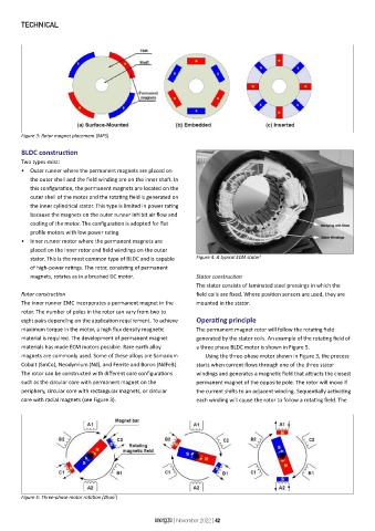
Figure 3: Rotor magnet placement (MPS)
BLDC construction
Two types exist:
• Outer runner where the permanent magnets are placed on
the outer shell and the field winding are on the inner shaft. In
this configuration, the permanent magnets are located on the
outer shell of the motor and the rotating field is generated on
the inner cylindrical stator. This type is limited in power rating
because the magnets on the outer runner inhibit air flow and
cooling of the motor. The configuration is adopted for flat
profile motors with low power rating.
• Inner runner motor where the permanent magnets are
placed on the inner rotor and field windings on the outer
stator. This is the most common type of BLDC and is capable Figure 4: A typical ECM stator 5
of high-power ratings. The rotor, consisting of permanent
magnets, rotates as in a brushed DC motor. Stator construction
The stator consists of laminated steel pressings in which the
Rotor construction field coils are fixed. Where position sensors are used, they are
The inner runner EMC incorporates a permanent magnet in the mounted in the stator.
rotor. The number of poles in the rotor can vary from two to
eight pairs depending on the application requirement. To achieve Operating principle
maximum torque in the motor, a high flux density magnetic The permanent magnet rotor will follow the rotating field
material is required. The development of permanent magnet generated by the stator coils. An example of the rotating field of
materials has made ECM motors possible. Rare earth alloy a three phase BLDC motor is shown in Figure 5.
magnets are commonly used. Some of these alloys are Samarium Using the three-phase motor shown in Figure 3, the process
Cobalt (SmCo), Neodymium (Nd), and Ferrite and Boron (NdFeB). starts when current flows through one of the three stator
The rotor can be constructed with different core configurations windings and generates a magnetic field that attracts the closest
such as the circular core with permanent magnet on the permanent magnet of the opposite pole. The rotor will move if
periphery, circular core with rectangular magnets, or circular the current shifts to an adjacent winding. Sequentially activating
core with radial magnets (see Figure 3). each winding will cause the rotor to follow a rotating field. The
Figure 5: Three-phase motor rotation (Zhao )
2
energize | November 2022 | 42